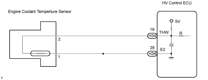
DTC P0115 Engine Coolant Temperature Circuit Malfunction |
DTC P0117 Engine Coolant Temperature Circuit Low Input |
DTC P0118 Engine Coolant Temperature Circuit High Input |
| DTC No. | Proceed to | DTC Detection Condition | Trouble Area |
| P0115 | Step 1 | Open or short in Engine Coolant Temperature (ECT) sensor circuit for 0.5 seconds (1 trip detection logic) |
|
| P0117 | Step 4 | Short in Engine Coolant Temperature (ECT) sensor circuit for 0.5 seconds (1 trip detection logic) |
|
| P0118 | Step 2 | Open in Engine Coolant Temperature (ECT) sensor circuit for 0.5 seconds (1 trip detection logic) |
|
| Temperature Displayed | Malfunction |
| -40°C (-40°F) | Open circuit |
| 140°C (284°F) or higher | Short circuit |
| 1.READ VALUE USING INTELLIGENT TESTER (ENGINE COOLANT TEMPERATURE) |
Connect the intelligent tester to the DLC3.
Turn the ignition switch ON.
Turn the tester ON.
Enter the following menus: Powertrain / Engine / Data List / Coolant Temp.
Read the value displayed on the tester.
| Temperature Displayed | Proceed to |
| -40°C (-40°F) | A |
| 140°C (284°F) or higher | B |
| Between 80°C and 97°C (176°F and 207°F) | C |
|
| ||||
|
| ||||
| A | |
| 2.READ VALUE USING INTELLIGENT TESTER (CHECK FOR OPEN IN WIRE HARNESS) |
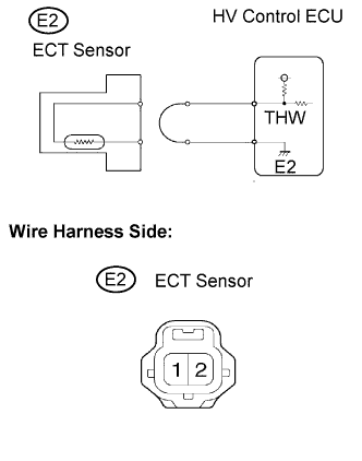 |
Remove the w/ converter inverter assembly (Click here).
Disconnect the E2 Engine Coolant Temperature (ECT) sensor connector.
Connect terminals 1 and 2 of the ECT sensor connector on the wire harness side.
Connect the intelligent tester to the DLC3.
Turn the ignition switch ON.
Turn the tester ON.
Enter the following menus: Powertrain / Engine / Data List / Coolant Temp.
Read the value displayed on the tester.
Reconnect the ECT sensor connector.
Reinstall the w/ converter inverter assembly (Click here).
Clear the DTC of the HV control system (Click here).
|
| ||||
| NG | |
| 3.READ VALUE USING INTELLIGENT TESTER (CHECK FOR OPEN IN ECM (INCLUDED IN HV CONTROL ECU)) |
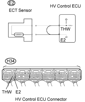 |
Remove the w/ converter inverter assembly (Click here).
Disconnect the E2 ECT sensor connector.
Connect terminals THW and E2 of the H34 HV Control ECU connector.
Connect the intelligent tester to the DLC3.
Turn the ignition switch ON.
Turn the tester ON.
Enter the following menus: Powertrain / Engine / Data List / Coolant Temp.
Read the value displayed on the tester.
Reconnect the ECT sensor connector.
Reinstall the w/ converter inverter assembly (Click here).
Clear the DTC of the HV control system (Click here).
|
| ||||
| NG | ||
| ||
| 4.READ VALUE USING INTELLIGENT TESTER (CHECK FOR SHORT IN WIRE HARNESS) |
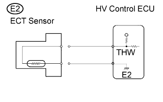 |
Remove the w/ converter inverter assembly (Click here).
Disconnect the E2 ECT sensor connector.
Connect the intelligent tester to the DLC3.
Turn the ignition switch ON.
Turn the tester ON.
Enter the following menus: Powertrain / Engine / Data List / Coolant Temp.
Read the value displayed on the tester.
Reconnect the ECT sensor connector.
Reinstall the w/ converter inverter assembly (Click here).
Clear the DTC of the HV control system (Click here).
|
| ||||
| NG | |
| 5.READ VALUE USING INTELLIGENT TESTER (CHECK FOR SHORT IN ECM (INCLUDED IN HV CONTROL ECU) ) |
 |
Remove the w/ converter inverter assembly (Click here).
Disconnect the H34 HV Control ECU connectors.
Connect the intelligent tester to the DLC3.
Turn the ignition switch ON.
Turn the tester ON.
Enter the following menus: Powertrain / Engine / Data List / Coolant Temp.
Read the value displayed on the tester.
Reconnect the HV Control ECU connector.
Reinstall the w/ converter inverter assembly (Click here).
Clear the DTC of the HV control system (Click here).
|
| ||||
| NG | ||
| ||
