DTC C0200/31 Front Speed Sensor RH Circuit |
DTC C0205/32 Front Speed Sensor LH Circuit |
DTC C1271/71 Low Output Signal of Front Speed Sensor RH (Test Mode DTC) |
DTC C1272/72 Low Output Signal of Front Speed Sensor LH (Test Mode DTC) |
| DTC No. | INF Code | DTC Detection Condition | Trouble Area |
| C0200/31 | 251 | At a vehicle speed of 6 mph (10 km/h) or more, an open or short in the sensor signal circuit of the abnormal wheel continues for 1 second or more. |
|
| ↑ | 252 | More than 1 wheel is abnormal. | ↑ |
| ↑ | 253 | Speed sensor signal circuit is open for 0.5 seconds or more. | ↑ |
| ↑ | 254 | Momentary interruption of sensor signal from the abnormal wheel occurs 255 times or more. | ↑ |
| ↑ | 255 | Frequency of 2.7 kHz or higher is input. |
|
| ↑ | 256 | Rotating direction of each wheel changes 7 times with the ignition switch on while driving at 6 mph (10 km/h) or more. |
|
| ↑ | 257 | Rotating direction of one of the wheels is not the same as that of the other wheels for 1 second while driving at 18 mph (30 km/h) or more. | ↑ |
| ↑ | 258 | Rotating direction of one of the wheels is not detected normally, and the rotating direction of each of the other wheels is not the same for 1 second while driving at 18 mph (30 km/h) or more. | ↑ |
| ↑ | 259 | 3 of the wheel sensors detect normal reversing signals, and the other wheel sensor detects malfunction signals 75 times with the ignition switch on while reversing at 1.8 mph (3 km/h). | ↑ |
| ↑ | 260 | At a vehicle speed of 6 mph (10 km/h) or more, the output from the vehicle speed sensor is halved for 5 seconds or more. | ↑ |
| ↑ | 261 | Reversing signal is output for 1 second or more while driving at 60 mph (100 km/h) or more. | ↑ |
| ↑ | 262 | With the voltage of IG1 terminal 9.5 V or more, the sensor power supply voltage decreases for 0.5 seconds or more. |
|
| C0205/32 | 264 | At a vehicle speed of 6 mph (10 km/h) or more, an open or short in the sensor signal circuit of the abnormal wheel continues for 1 second or more. |
|
| ↑ | 265 | More than 1 wheel is abnormal. | ↑ |
| ↑ | 266 | Speed sensor signal circuit is open for 0.5 seconds or more. | ↑ |
| ↑ | 267 | Momentary interruption of sensor signal from the abnormal wheel occurs 255 times or more. | ↑ |
| ↑ | 268 | Frequency of 2.7 kHz or higher is input. |
|
| ↑ | 269 | Rotating direction of each wheel changes 7 times with the ignition switch on while driving at 6 mph (10 km/h) or more. |
|
| ↑ | 270 | Rotating direction of one of the wheels is not the same as that of the other wheels for 1 second while driving at 18 mph (30 km/h) or more. | ↑ |
| ↑ | 271 | Rotating direction of one of the wheels is not detected normally, and the rotating direction of each of the other wheels is not the same for 1 second while driving at 18 mph (30 km/h) or more. | ↑ |
| ↑ | 272 | 3 of the wheel sensors detect normal reversing signals, and the other wheel sensor detects malfunction signals 75 times with the ignition switch on while reversing at 1.8 mph (3 km/h). | ↑ |
| ↑ | 273 | At a vehicle speed of 6 mph (10 km/h) or more, the output from the vehicle speed sensor is halved for 5 seconds or more. | ↑ |
| ↑ | 274 | Reversing signal is output for 1 second or more while driving at 60 mph (100 km/h) or more. | ↑ |
| ↑ | 275 | With the voltage of IG1 terminal 9.5 V or more, the sensor power supply voltage decreases for 0.5 seconds or more. |
|
| 1.CHECK HARNESS AND CONNECTOR (MOMENTARY INTERRUPTION) |
Using the intelligent tester, check for any momentary interruption in the wire harness and connector corresponding to a DTC (Click here).
| Item | Measurement Item / Range (Display) | Normal Condition |
| FR Speed Open | FR speed sensor open detection / NORMAL or ERROR | NORMAL : Normal condition |
| FL Speed Open | FR speed sensor open detection / NORMAL or ERROR | NORMAL : Normal condition |
|
| ||||
| OK | |
| 2.READ VALUE OF INTELLIGENT TESTER (FRONT SPEED SENSOR) |
Connect the intelligent tester to the DLC3.
Turn the ignition switch ON position.
Select the DATA LIST mode on the intelligent tester.
| Item | Measurement Item / Range (Display) | Normal Condition |
| FR Wheel Speed | Wheel speed sensor (FR) reading / min.: 0 km/h (0 MPH), max.: 326 km/h (202 MPH) | Actual wheel speed |
| FL Wheel Speed | Wheel speed sensor (FL) reading / min.: 0 km/h (0 MPH), max.: 326 km/h (202 MPH) | Actual wheel speed |
Check that there is no difference between the speed value output from the speed sensor displayed on the intelligent tester and the speed value displayed on the speedometer when driving the vehicle.
|
| ||||
| NG | |
| 3.INSPECT FRONT SPEED SENSOR INSTALLATION |
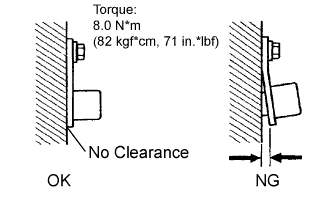 |
Check the sensor installation.
|
| ||||
| OK | |
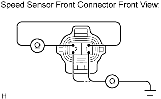
| 4.INSPECT FRONT SPEED SENSOR |
 |
Make sure that there is no looseness at the connector's locking part and connecting part of the connector.
Disconnect the speed sensor connector.
Measure the resistance according to the value(s) in the table below.
| Tester Connection | Specified Condition |
| 2 (FL+) - 1 (FL-) | 1.4 to 1.8 kΩ |
| Tester Connection | Specified Condition |
| 2 (FR+) - 1 (FR-) | 1.4 to 1.8 kΩ |
Measure the resistance according to the value(s) in the table below.
| Tester Connection | Specified Condition |
| 1 (FL-) - Body ground | 10 kΩor higher |
| 2 (FL+) - Body ground | 10 kΩor higher |
| Tester Connection | Specified Condition |
| 1 (FR-) - Body ground | 10 kΩor higher |
| 2 (FR+) - Body ground | 10 kΩor higher |
|
| ||||
| OK | |
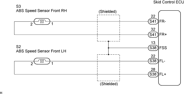
| 5.CHECK HARNESS AND CONNECTOR (BETWEEN FRONT SPEED SENSOR AND SKID CONTROL ECU) |
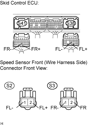 |
Disconnect the skid control ECU connectors and the front speed sensor connectors.
Measure the resistance according to the value(s) in the table below.
| Tester Connection | Specified Condition |
| S2-1 (FL-) - S38-22 (FL-) | Below 1 Ω |
| S2-2 (FL+) - S38-28 (FL+) | Below 1 Ω |
| Tester Connection | Specified Condition |
| S3-1 (FR-) - S41-22 (FR-) | Below 1 Ω |
| S3-2 (FR+) - S41-32 (FR+) | Below 1 Ω |
Measure the resistance according to the value(s) in the table below.
| Tester Connection | Specified Condition |
| S2-2 (FL+) - Body ground | 10 kΩ or higher |
| S2-1 (FL-) - Body ground | 10 kΩ or higher |
| Tester Connection | Specified Condition |
| S3-2 (FR+) - Body ground | 10 kΩ or higher |
| S3-1 (FR-) - Body ground | 10 kΩ or higher |
|
| ||||
| OK | |
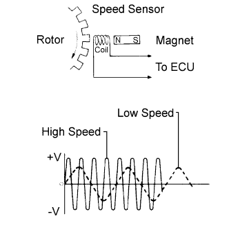
| 6.INSPECT SPEED SENSOR AND SENSOR ROTOR SERRATIONS |
 |
Connect the skid control ECU connectors.
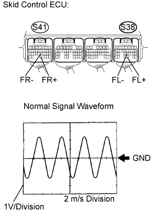
Connect the oscilloscope to terminals S41-32 (FR+) and S41-22 (FR-) or S38-28 (FL+) and S38-22 (FL-) of the skid control ECU.
Drive the vehicle at approximately 19 mph (30 km/h), and check the signal waveform.
|
| ||||
| OK | |
| 7.READ VALUE OF INTELLIGENT TESTER |
Connect the intelligent tester to the DLC3.
Turn the ignition switch on.
Select the DATA LIST mode on the intelligent tester.
| Item | Measurement Item / Range (Display) | Normal Condition |
| FR Wheel Speed | Wheel speed sensor (FR) reading / min.: 0 km/h (0 MPH), max.: 326 km/h (202 MPH) | Actual wheel speed |
| FL Wheel Speed | Wheel speed sensor (FL) reading / min.: 0 km/h (0 MPH), max.: 326 km/h (202 MPH) | Actual wheel speed |
Check that there is no difference between the speed value output from the speed sensor displayed on the intelligent tester and the speed value displayed on the speedometer when driving the vehicle.
|
| ||||
| OK | ||
| ||
| 8.PERFORM TEST MODE (SIGNAL CHECK) |
Perform sensor signal check in TEST MODE PROCEDURE (Click here).
|
| ||||
| OK | |
| 9.INSPECT SPEED SENSOR AND SENSOR ROTOR SERRATIONS |
|
Connect the oscilloscope to terminals S41-32 (FR+) and S41-22 (FR-) or S38-28 (FL+) and S38-22 (FL-) of the skid control ECU.
Drive the vehicle at approximately 19 mph (30 km/h), and check the signal waveform.
|
| ||||
| OK | ||
| ||
| 10.REPAIR OR REPLACE HARNESS OR CONNECTOR (BETWEEN FRONT SPEED SENSOR AND SKID CONTROL ECU) |
| NEXT | |
| 11.RECONFIRM DTC |
Clear the DTC (Click here).
Turn the ignition switch on.
Drive the vehicle at the speed of 32 km/h (20 mph) or more, for 60 seconds or more, and drive in reverse at a speed of 3 km/h (2 mph) or more, for approximately 5 seconds.
Check that the same DTC is recorded (Click here).
| Condition | Proceed To |
| DTC is not output | A |
| DTC is output | B |
|
| ||||
| A | ||
| ||
