DTC Code
| INF Code
| DTC Detection Condition
| Trouble Area
|
U0073/94
| 461
| Either of the following is detected:
- Yaw rate and acceleration sensor communication is disabled for 1 second or more.
- Yaw rate and acceleration sensor communication is disabled once or more per 5 seconds 10 times or more within 60 seconds.
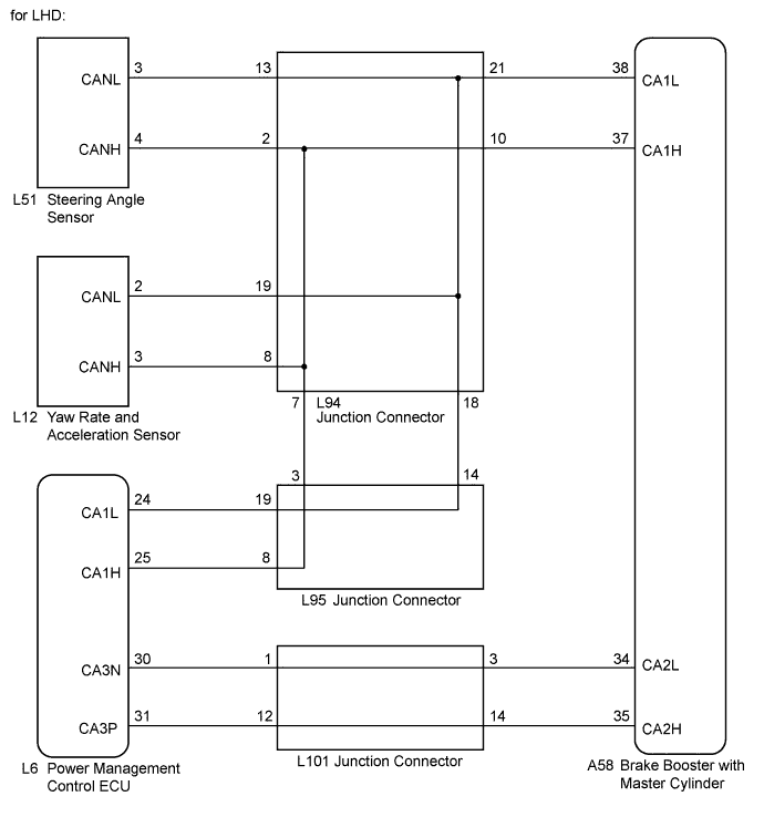
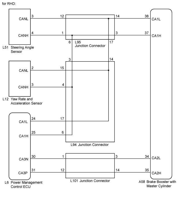
| - CAN communication line (CAN No. 1 bus)
- Yaw rate and acceleration sensor
- Brake booster with master cylinder (Skid control ECU)
|
↑
| 462
| Either of the following is detected:
- Steering angle sensor communication is disabled for 1 second or more.
- Steering angle sensor communication is disabled once or more per 5 seconds 10 times or more within 60 seconds.
| - CAN communication line (CAN No. 1 bus)
- Steering angle sensor
- Brake booster with master cylinder (Skid control ECU)
|
↑
| 463
464
| Bus off occurs once or more per 0.1 seconds 10 times repeatedly.
| - CAN communication line
- Brake booster with master cylinder (Skid control ECU)
|
↑
| 465
466
| Sending does not complete within 5 seconds after data is output from the skid control ECU.
| ↑
|
U0123/62
| 731
| Yaw rate sensor communication is disabled for 1 second or more.
| - CAN communication line (CAN No. 1 bus)
- Yaw rate and acceleration sensor
- Brake booster with master cylinder (Skid control ECU)
|
↑
| 732
| Yaw rate sensor communication is disabled once or more per 5 seconds 10 times or more within 60 seconds.
| ↑
|
U0124/95
| 591
| Acceleration sensor communication is disabled for 1 second or more.
| - CAN communication line (CAN No. 1 bus)
- Yaw rate and acceleration sensor
- Brake booster with master cylinder (Skid control ECU)
|
↑
| 592
| Acceleration sensor communication is disabled once per 5 seconds 10 times or more within 60 seconds.
| ↑
|
U0126/63
| 741
| Steering angle sensor communication is disabled for 1 second or more.
| - CAN communication line (CAN No. 1 bus)
- Steering angle sensor
- Brake booster with master cylinder (Skid control ECU)
|
↑
| 742
| Steering angle sensor communication is disabled once or more per 5 seconds 10 times or more within 60 seconds.
| ↑
|
U0293/59
| 411
412
413
| Either of the following is detected:
- With the IG2 terminal voltage 9.5 V or more, data from the power management control ECU cannot be received for 2 seconds or more.
- With the IG2 terminal voltage 9.5 V or more, data from the power management control ECU cannot be received once or more within 5 seconds occur 10 times in succession.
| - CAN communication line (Power management bus)
- Power management control ECU (Hybrid vehicle control ECU)
- Brake booster with master cylinder (Skid control ECU)
|